Today, I spent some time working on electrical.
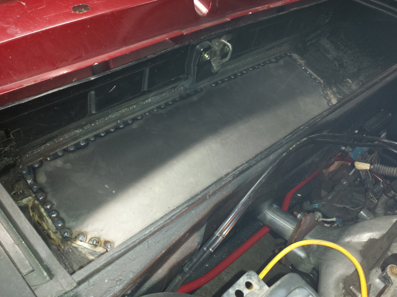
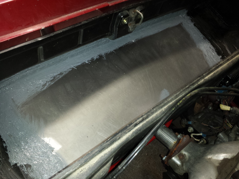
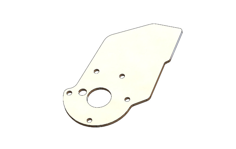
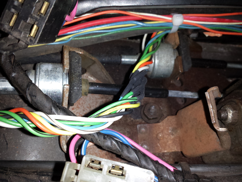
My power mirror switch backing plate was very loose and not making good contact. I cut one from a parts car and installed. Both power mirrors now work.
One more item checked off the "to do" list.
As you know, I've swapped in a 2.2 Ecotec into this car. Since I'm using the stock PCM and BCM, and not the Cavalier cluster, I needed to make the Equus aftermarket tachometer work with the Ecotec. Here's how I did it.
By looking at the 2003 Cavalier wiring schematic, a tachometer trigger signal is sent by the PCM through the serial data line and to the cluster where it's converted.
Since I'm not using the Cavalier cluster, I had to go about this another way.
Looking at the PID value charts was useless as it merely states, "Not Used" on several pins.
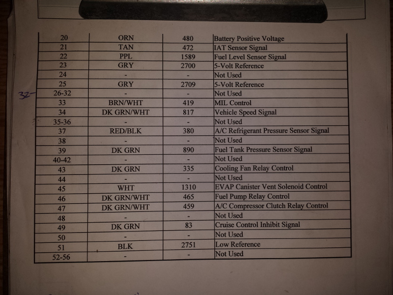
By using an oscilloscope, each pin labeled "not used" was checked.
Success was present when pin 32 on the blue connector showed an open collector output for a tachometer.
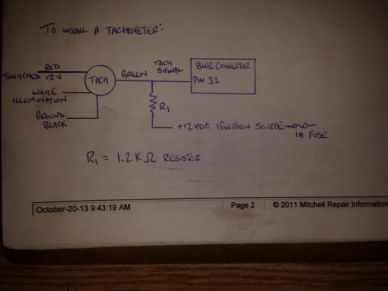
Since I had an aftermarket tach that doesn't have an internal "pull-up" resistor, I had to add one.
Note: I didn't have a 1K ohm (1000) resistor handy but I had some 1.2K (1200) ohm resistors in my collection.
The pull-up resistor pulls the open (collector) output up to +12V.
When the output transistor turns on, its collector terminal is connected to ground.
Hence the output is a square wave from near-ground to near +12V.
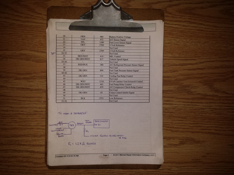
Here's the schematic that made it all work, simple really.
Note: I'm using PCM part # 12576162
Since pin 32 was not used, there was no wire coming from the connector. I took another PCM harness pig tail and removed a white wire.
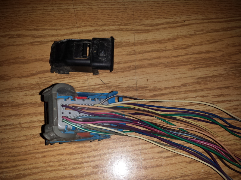
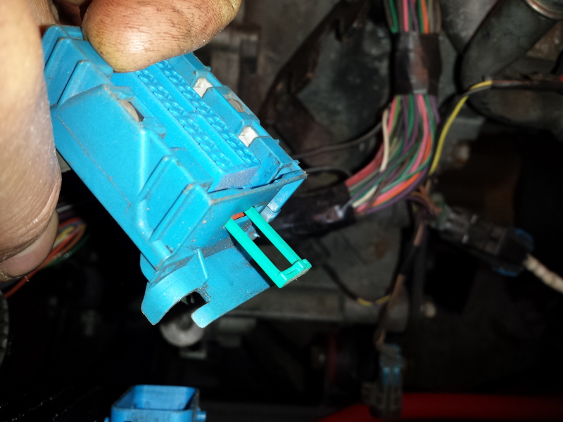
Remove the turquoise clip and unlock the connector.
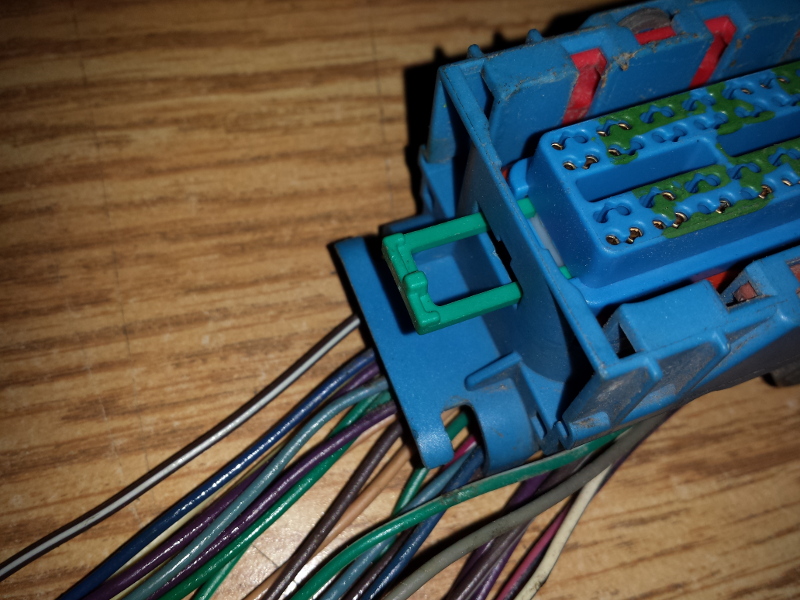
This leads to exposed terminals and wires. I took a white wire just because.
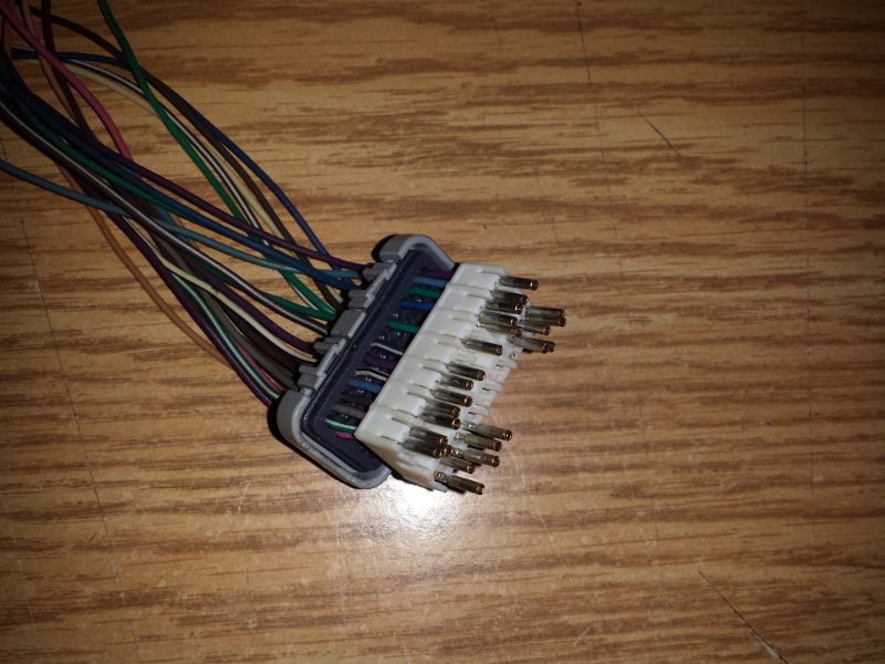
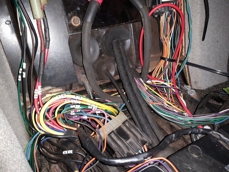
On the car, I had to undo the clip and disassemble the connector.
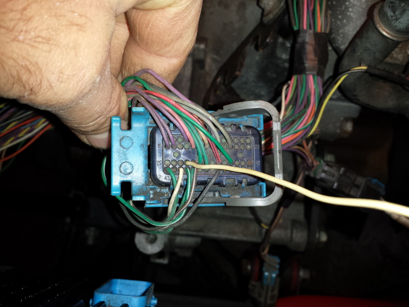
Since cavity 32 was unused, I had to drill a small hole in order to place the connector through.
Here, you can clearly see the white wire protruding from cavity 32 on the blue connector.
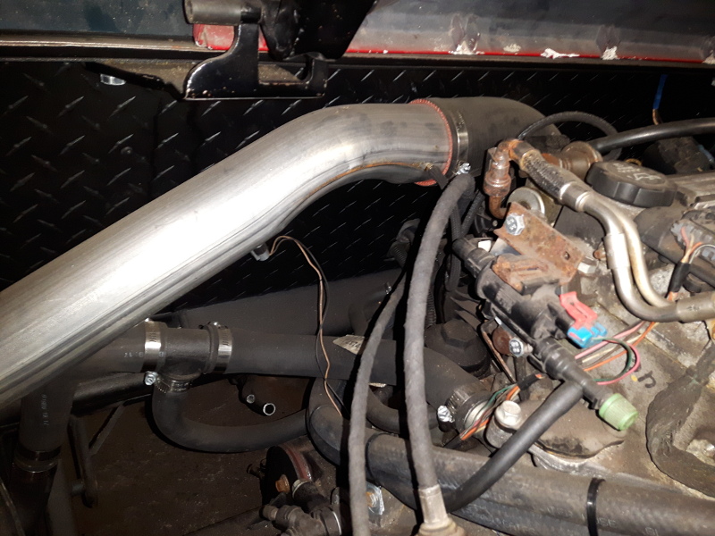
I extended this new white wire to the stock Fiero harness.
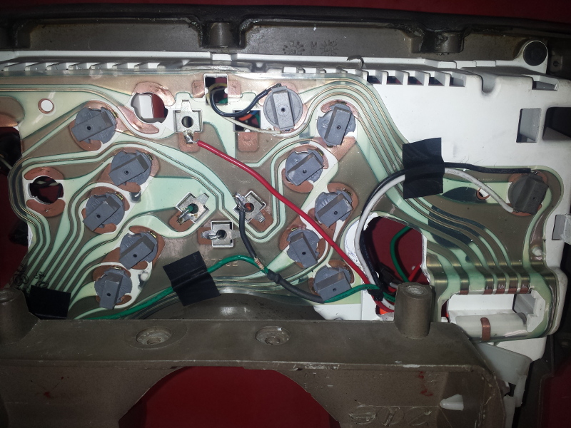
I then chose to add the pull-up resistor in the back of the instrument cluster.
In this location, I could tap into the two electrical points that I needed.
-The green wire is the tach signal wire.
-The resistor is then attached to the signal wire and the opposite end attaches to a keyed-on +12V.
A little video to show that it actually works.
http://www.youtube.com/watch?v=KihE5I_jdC8